Requirement
Most recent BEN2 activity has been focussed on creating a user-friendly development environment.
We used a couple of VIA pins for our ROM-writing program and that only leaves three VIA pins available for LEDs, buttons and other things.
Adding an extra VIA would require me to sort out addressing logic (chips and wiring) to reserve a new address range for the second VIA so it would create major upheaval. A less extreme alternative would be to change my LCD logic from the 8 to the 4 pin version. However that would only give me four extra lines.
I prefer an option described by Garth Wilson which utilises the shift register function built into the 6522 VIA.

Shift Registers
Shift registers are commonly used for serial to parallel (SIPO) and parallel to serial (PISO) conversion.
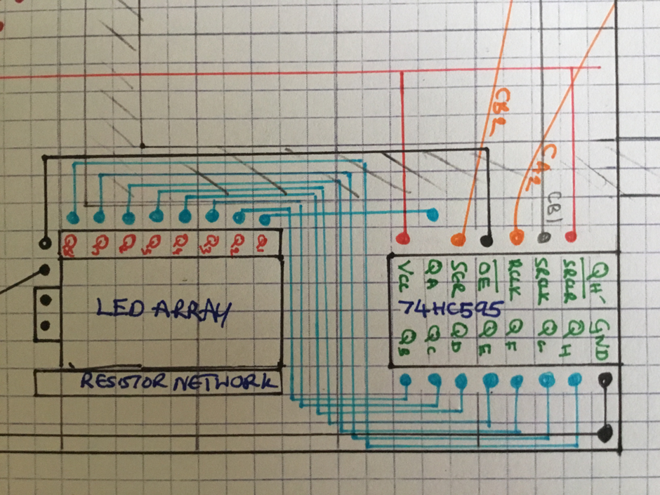
The diagram above shows 74HC595 shift registers being used for SIPO. A stream of 8 bits is sent from the VIA chip to a 595. The 595 then latches the 8 bits to its output lines which can have LEDs or other output devices attached. We only need three VIA pins to send the data. Even better we can daisy chain the 595s so that we have 8,16,24, 32,....outputs.
The diagram above shows 74HC595 shift registers being used for SIPO. A stream of 8 bits is sent from the VIA chip to a 595. The 595 then latches the 8 bits to its output lines which can have LEDs or other output devices attached. We only need three VIA pins to send the data. Even better we can daisy chain the 595s so that we have 8,16,24, 32,....outputs.
Shift register operation is quite straightforward, I learned a bit more from a random article for the Onion SBC which provided the schematic below. Individual bits (on pin 14) are transmitted into the register, at each clock pulse ( on pin 11). At an appropriate time they are latched (using pin 12) to a "storage register" so that the output can be used. For our purposes the VIA will organise a stream of 8 bits on the CB2 pin with a clock signal on CB1. When the 8 bits are in the 595 SR we will set CA2 high to latch these to Storage Register Outputs.

This seems a fine way to proceed so that we can add some LEDs, or other outputs and I purchased some 74HC595 chips from ebay for £0.60 each.
I dont foresee much need for more inputs but I could use 74HC165 shift registers provide PISO conversion. One application area which could utilise this solution would be dip switches, each of which requires a line.
Connections
A good tutorial from DroneBotWorkshop provides pinouts for 74HC595

Programming
With the wiring in place, we need a BEN2 program which will cause the W65C22 VIA to send appropriate signals to the '595. Garth Wilson provides some guidance on his web page. We need to use three W65C22 registers
Shift Register (SR)
Auxiliary Control Register (ACR)
Peripheral Control register (PCR)
Firstly, using PCR we set CA2 low, so there is no output from the '595.
Next we configure the 6522 to use the 6502 system clock (PHI2) to pulse serial bits to '595 as shown in the 6522 datasheet timing manual

it is sent to '595 and as soon as we pulse CA2 high the data is output to LEDs.
The code is shown below, there is an init subroutine and a display subroutine. I put a short delay in the display subroutine so that 6502 waits for bits to be transferred before they are displayed.

Result
This was an enjoyable and rewarding days work. I have expanded the output capabilities of the system, adding 8 LEDs with very little effort. Even better I could daisy chain a number of 74HC595 chips to add as many as I want.
No comments:
Post a Comment