Saturday 31 December 2022

My Top Ten Favourite Pictures

 A tricky question

I started off trying to decide my top ten favourite pictures, but realised it is pretty impossible to choose a list.  I Googled top ten and mostly I don't particularly like them.  Do I prefer old to modern artists, pictures showing skilled brushstrokes, is the immediate impact or story told important and how much should knowledge of the artist/picture/environment/rarity/history be important?  I appear to have another impossible task.  Annette suggested picking my two favourite artists from each century but even this proved a headache. 

Criteria

I think my main criteria are:

  • how much or how long I enjoy looking at a picture
  • is the composition interesting
  • are the colours expressive
  • whether it is an enduring opinion rather than a whim
  • is there an interesting story
  • does it have a strong emotional effect
  • is its rarity/age admirable
  • is great skill evident
  • does the work communicate a strong message 

My approach

I have a photo collection from the principal galleries I have visited so I will restrict myself to choosing from the pictures on my website.  Even so there is a great variety to choose from, I find it hard even to compare artists from different times.  My approach will be a sort of knock-out tournament.  When deciding which images to capture for my website I aim to choose about four per room and each gallery comprises a number of groups of rooms.  I will start the first round by choosing four pictures per group and move on in the second round to choose four of the winners to get the top four pictures in a gallery.  Galleries and Galley exhibitions are classified separately so I will end up with about 10 groups of four in the semi-final.

A snapshot

A selection of my favourite art based on those I like best and I have pinned up, in miniature, on my study wall.

1 Wheatfield with Crows, Vincent Van Gogh 1890

2 Claude Monet, Water-lilies, Setting Sun 1907

3 The Fighting Temeraire, JMW Turner 1838

4 Ballet Dancers, Degas, 888


5 Debbie Harry, Andy Warhol, 1980

6 An experiment on a bird, Joseph Wright of Derby 1768

7 Lake Keitele, Akseli Gallen-Kallela, 1905

8 Hylas surprised b Naiades, John Gibson, 1827

9 Salome, Aubrey Beardsley, 1893

10 Magna Carta (an Embroidery), Cornelia Parker, 2015


Thursday 29 December 2022

Top Ten Best Pictures in the world

What are the ten best artworks in the world?  It isn't easy to say, even with Google's infinite resources. It seems that Lady with Pearl Earrings, by Vermeer, is one of the most famous and Da Vinci's Mona Lisa is usually top of the list.  I certainly wouldn't put them amongst my favourites and it started me thinking.

It isn't possible to define simple criteria for a "best" painting as it is a very subjective opinion based on individual preferences, knowledge, outlook, culture and expertise. A suitable substitute is to search for "most famous" which might indicate some limited consensus for excellence.

I looked at a number of search results for "10 most famous paintings" and came up with the list shown below; it is mainly based on a CNN style article with some images reproduced fron Wikimedia Commons.  As a separate exercise, on another blog entry, I will try to choose my 10 favourite paintings that I have seen/photographed.   The overlap between the two lists will be minimal.

1 Mona Lisa, Leonardo da Vinci, 1503
2 The Last Supper, Leonardo Da Vinci,1495 


3 The Starry Night, Vincent van Gogh,1889 

4 The Scream, Edvard Munch, 1893


5 Guernica, Pablo Picasso, 1937 

6 The Kiss, Gustav Klimt, 1907

7 Girl with a pearl earring, Vermeer, 1665

8 The Birth of Venus, Sandro Botticelli, 1485

9 Water Lilies, Monet, 1906

10 The Persistence of Memory, Salvador Dali, 1931


Wednesday 21 December 2022

Chromecast

About eight years ago we purchased a small Samsung "Smart TV".  At the time we thought it was very clever as it has an ethernet connection which allowed us to use an inbuilt web browser and iPlayer.  Subsequently  it was used as a computer screen and to play media from a DLNA server.

I now want to integrate it with Home Assistant so that we can start and control videos as we do for music.  Unfortunately the Smart TV is not smart enough for this so I purchased a Chromecast to help it.

Chromecast installation and testing

As expected there is a slick installation procedure and I soon have the Chromecast working on HDMI with the usual apps such as Netflix, ITVhub available.  

Chromecast provides extra connectivity capabilities.
We can easily cast youtube or iplayer from the phone to Chromecast.
On the ipad we can cast from youtube, vlc or iplayer.
On the PC we can cast a chrome browser session to the TV allowing us to see whatever is displayed or playing in the browser.  Alternatively you can cast videos from the youtube app or vlc.
All these facilities are great but I probably wouldn't use them much in practice, so I now need to see what extras Home Assistant can offer.

Home Assistant

HA has a Google Cast integration built in and uses it to send speech or music to the Google Nest mini.  As far as HA is concerned the TV, with Chromecast attached, is just another casting device.


Using the "Browse Media" button on the card for the TV you can select a video from the DLNA server or local media and play it on the TV.  This is a great start, we can already play videos of our choice and it is as simple to use from HA as it is selecting DLNA directly on the TV.

Looking at the sample in Google Cast integration  it is easy to setup a script to cast a video to the TV.  The service is media_player.play_media, the target is media_player.john_study_tv and you just need to provide a URL and type for the media content. Running this script causes the video to play.  Now that I have a script I can use a webhook or Google Assistant command to initiate the video so I have the basis of a solution.


Clearly it is rather limiting if I have to setup a script for each video I want to play so I setup a helper, called xmas_anthem for testing.  I can can setup a number of valid options for xmas_anthem and set the value on a dashboard card.  Within the script I can now test input_select.xmas_anthem to determine which video to play.

You can also play youtube videos by specifiying suitable media_content details:


Since our first test was to play a video from DLNA it must also be possible to specify a DLNA video as the media_content.  This doesn't seem to be simple.  When looking at a DLNA video playing I can see that the media_content_id is a URL containing a numeric value (5240.mkv in the example shown below) rather than a filename.   To determine these values I would need to interrogate the DLNA server.  I have a python script which sort of does this but it doesn't work well yet.

Conclusion

I now have the tools I need to play videos on a TV, namely ChromeCast and Home Assistant scripts.  The next stage is to work out what videos I want and setup a webpage or voice commands to play them.


Sunday 6 November 2022

MangoPi


The MangoPi MQ Pro came to my attenion on the Telegram forum, in particular Daniel Maslowski, on 22JUL22, provided a link to a review by "Bret".  It appeared to be very similar to the Nezha and LicheeRV systems.  It contains a D1 chip and 1GB memory, It seems almost as powerful as the Nezha but at about half the price.  I purchased one from AliExpress for £42.89, including VAT and shipping and it arrived 10AUG22.

The system is v1.4, apparently the first production build.  It is a noticeable "Sakura Pink" colour and comes with a convenient colour coded header.


It is the same form factor as a RaspberryPi zero so I ordered a cheap (£4) case on Ebay.  It fits very well, although you cant change the SD card without removing the case.


Mangopi.org is the home website and it contains some basic information about the hardware.  It provides links to Tina and Armbian images.  Bret.dk provides a much better introduction so I followed his instructions to download and install the Armbian headless image.

For the first startup I need an HDMI screen plus keyboard.  Unfortunately I don't have a mini-HDMI adapter so I had to buy one.  Also I couldn't plug my USB-USBC adapter in at the same time as the power so I had to by a pretty little hub, which I am sure will come in very useful as more systems move to USBC

With all the necessary hardware ready and an Armbian SD card inserted all I needed to do was startup.  This went like a dream.  I was very pleasantly surprised that the startup asked me for wifi details and then configured a DHCP IP address for me.

With this in place I can sign in through SSH and I can access the Ubuntu system.The apt command for update/upgrade work fine so I count this as a functional system 😁😀😃

LicheeRV Compatibility

There are indications (not sure where) that MangoPi is compatible with the other Allwinner D1 systems, Nezha and LicheeRV.  My idea of compatibility is to put an SD card in and see what happens.  Before doing this I needed to solder on the header pins and attach an FTDI cable so I can use a serial interface to see boot messages.  There is no documentation on MangoPi pins but the spec says that it is an RPI header so I guessed that the pins required are 6=GND, 8=TXD, 10=RXD.  This is indeed the case and booting the Armbian system shows me the early console messages (before HDMI is initialised).

MangoPi uses an RTL8273DS chip for wifi which is the same as used by LicheeRV.  So, when I booted from my usual LicheeRV SD card the system came up cleanly (and a lot faster).  Wifi is initialised properly and static address/SSH access work fine.  This is great, it means I have a Debian system for my MangoPi - without doing any work.


Monday 10 October 2022

6502 : Move to a processor board

 It is great to have a working circuit outputting to a terminal screen and we need to work on it, primarily to speed it up using a real clock and to do proper input/output.

My initial attempts to speed the circuit up were unreliable necessitating wiring checks amongst other tests.  In fact I am not sure why the circuit was unreliable, it could have been wiring, or my Arduino nano clock or the ACIA/terminal session hanging.  At any rate the reason for using soldered boards is to prevent wiring issues and this led me to build a second board for the CPU, ACIA and control logic.

For the new board I chose an alternative strip board which provided me with 4 connection holes available on each side of the 6502 / ACIA  chips.  This makes CPU/ACIA connections much easier to specify.

The only downside is that I dont have +5V and GND rails provided for me so I have to "daisy chain" power connections.  I underestimated the work involved with these and had to amend the design during soldering.  In future I should allocate some spare tracks for power wires.  Other than this problem the soldering is easier than the memory board as a lot of address wires are not required on the board.  Off board connections are provided from the CPU to the memory board.  There is also a spare row so that I can add a lower row of chips in the spare space at the bottom of the board and connect them to the CPU.

Once the board was soldered I could check the quality as usual by testing sdjacent shorts and circuit testing each board connection to make sure there was conductivity.  Annoyingly there was one short which I missed and I later had to take everything apart to check it again later.


With soldering finished I could connect the new processor board to the memory board using dupont ribbon cables and test functionality using the same Arduino Mega sketches which I used to develop the breadboard version.  Having a structured set of tests makes the process a lot easier.  As mentioned above there was a shorted connection which meant the read-write pin was always in write-mode stopping the CPU from running.  Once this was corrected and I had a working board I could attach my boards to their perspex backing board, hopefully making this a more permanent board.


The board isn't nearly as elegant as I thought it would be but I am hoping it will be more reliable.  On the picture you can see that the memory board is above the processor board and there is more space below for other components / boards.
At this stage the Mega is still connected.  It is needed to download programs into ROM.  Eventually I hope we will have a stable monitor program in ROM which is capable of downloading programs to RAM for testing.

It can also be seen on the picture that the clock is separate.  Initially I have used Ben Eaters 555 timer based clock but it only runs upto 500Hz.  The W65C02 is capable of running at 1 MHz or more so I have a 1 MHz clock chip.  However if I just substitute the 1 MHz clock for the Ben clock it doesn't work.  I need to be able to slow down the 1 MHz clock to see how fast I can run it.  To do this I purchased some CD4020 binary counter chips.  Using one of these chips I can reduce the clock speed by a factor of 32768 to about 30Hz.  Using a second counter I can reduce the speed further.

My breadboard version of the circuit worked upto about 5000Hz, first tests on the new processor board indicate that it will work upto 50KHz or more which is what I really wanted to see from this exercise.

Postscript 

[November 2022]The story didn't have a happy ending!  I couldn't get the ACIA serial interface to work reliably and progress on writing software slowed to a halt.  DON is now on hold.  The next step may possibly be careful debugging, but is more likely to be a replacement board.

Sunday 11 September 2022

6502 Terminal

ACIA Serial Chip

My working 6502 system needs some input / output capability.  Ben Eater added a VIA (Versatile Interface Adapter) and attached an LCD display to his system.  I prefer to start with an ACIA (Asynchronous Communication Interface Adapter).  This provides me with a serial interface running at 19200 baud.

An ACIA chip was added to the breadboard and connected using an FTDI chip to a PC USB COM port.  The hardware allows me to use a Windows Terminal or Putty session providing a screen and keyboard interface.  I could attach a physical terminal, but they don't really exist anymore and a PC terminal session works just fine.  I did build a physical terminal using an LCD screen a while ago but I don't need it here.

Arduino Testing

My inspiration for the ACIA connection is Dirk Grappendorf who provides an excellent description and code to terminal I/O.  

To check my breadboard connections I designed a sketch which ran on the Mega without the need to use my CPU.  In fact I did have trouble getting the ACIA to work as an extra capacitor is required which Herr Grappendorf mentioned but I omitted as it wasn't shown on the datasheet.

The ACIA is controlled in a very simple manner.  Two bytes are written to the command and control registers specifying communication parameters.  Subsequently bytes which are inserted in the transmission register are sent to the FTDI and onwards to the PC terminal session.

6502 Machine Code


Once I was happy that wires and the ACIA were working I could write a very simple assembly program which writes the command register (address $4002) the control register (address $4003) and then loops to output a character (0x34, the digit 4) in the data register (address $4000).


The result is a 17 byte program which puts a steady stream of characters out on the terminal.  There isn't any synchronisation by the program to ensure that the terminal is ready for the next character before transmitting it, we simply send characters as fast as we can.


Add RAM

We dont actually require RAM for this version of the program to work.  RAM is required for the 6502 stack, which is used by the subroutine mechanism to store return addresses.  Adding a subroutine to the program allows us to check that RAM is still working.

Clock Speed

Initial testing is carried out using the Ben Eater clock, which is a 555 timer based solution which runs at speeds upto about 200Hz.  Previously I have built an Arduino nano-based clock which allows me to choose between a number of speeds 5 Hz, 50 Hz, 500 Hz and 5000 Hz.  When I substituted the nano clock into the system I found that it worked.  However, as expected, the system didn't work when the full-speed 1 MHz clock chip was connected.

Summary  

We have added a terminal to our 6502 system so that we can do input / output.  We wrote a very simple machine code program as a first test that output to the terminal works.  Normally the "terminal driver" would synchronise transmission and receiving but we had good results with a 5 KHz clock sending characters as fast as we could.
What we really need is a software environment to assemble and load programs so that we can better, more extensive programs - this will come next.


Saturday 10 September 2022

6502 stripboard circuit

 It is almost a year since I touched my 6502 systems.  I decided to step away as reliability problems were frustrating me greatly.  In particular programs didn't run reliably with the 1 MHz clock and I suffered repeated loose connections.  God knows how Ben Eater copes with his bread board circuits, I guess he must be so meticulous that all his connections are reliable.

Options

I considered various options to make my system more "permanent" and less error-prone:
 * Design  a PCB for my components and get it made up
    - this is too complicated for a first PCB creation, very difficult to be 100% accurate
 * Buy a PCB designed for these components
    - I did find one that looked promising by Jeff Tranter but opted to try the W65C02SXB instead
 * Buy a W65C02SXB which contains all the components I need
    - I did buy a board, and it is wonderful, but it is somewhat different to use
 * Use stripboard to create a permanent version of my working breadboard circuit.
    - This is the most reasonable way forward and one I have put a lot of effort into.

Stripboard

Stripboard generally comes in boards upto 38 columns wide with long tracks.  This isn't very convenient for soldering ICs as all the tracks have to be cut under each chip.  There are a few stripboards available (I only really looked on eBay) in breadboard style format.and I have purchased some of each type.  The main requirement is to have at least two holes, preferably three, on either side  of the larger chips to solder connections.

Layout

In theory I could just copy my existing breadboard chips and connections to stripboard.  In practice the first boards I found were not as wide as breadboard (which has 63 holes across) so I needed a different arrangement.  In addition the existing breadboard components weren't necessarily in the best positions so there were some potential improvements I could make.

As ROM and RAM share address and data bus connections and I have previously had problems with them I decided to create a ROM-RAM memory board with a NAND chip for control logic and off-board  bus and control connections to the 6502.  As an Arduino Mega is used for testing and to program ROMs it is best connected to the memory board.  Offboard connections will be made using dupont connectors terminated in male posts on the board.

It was a hard days work to draw a board diagram with chip locations and all necessary connections. In particular I needed to make sure that all 6502 pins required both for memory chips and those used by the Mega were available. Clearly any errors preventing the board working would be difficult to correct once it had been soldered.


Build


As an amateur at this business it was obvious that I should build the board in stages.  The first stage is to solder EEPROM and Arduino Mega connections.  The Mega is used to write code to ROM and the ROM can work in isolation from NAND, RAM and CPU.  I inserted a ROM chip (AT28C256) with known code onto the board and checked I could read it from the Mega and then wrote some new code to the ROM and read it back.

We can now solder remaining board connections.  


The NAND chip is used to select either RAM or ROM.  Our simplified memory map is:
   $0000-$3FFF   RAM
   $8000-$FFFF   ROM
so we use the address wires A15 and A14 in the NAND gates to enable/disable ROM and RAM.
A sketch is used to check that NAND inputs provide the correct control signals to ROM and RAM.  Another sketch, which is very similar to the ROM read sketch can then test reading and writing RAM. 

We are now confident our memory works and it is time to add the W65C02 CPU to the circuit.  We are not yet ready for a soldered version so the CPU and reset button are put onto a breadboard.  The CPU needs a clock, for which the trusty Ben Eater Clock circuit is used.

At this stage we are not using RAM, program instructions are loaded from ROM and executed by the CPU.


A monitor sketch is devised, running on the Mega, which displays address and data bus values after each clock cycle.

The 6502 datasheet explains that when Reset is pressed the CPU uses 6 clock cycles to initialise and then loads a reset vector from address $FFFC and $FFFD.  On the right you can see that cycles 6 and 7 load an address $8000 from these addresses and executes the (non-existent) program starting at $8000.

In fact, we previously used a Mega sketch to store data in the reset vector $FFFC=0x00 and $FFFD=0x80.  The 6502 uses "little-endian" addresses, which means that the low order address byte is stored first.  and the high order byte second so these values are correctly interpreted as address $8000.

Program Execution


We now write a simple assembly program to write some data in a loop and load it into ROM starting at address $8000 using the Mega.  The address values $6000 and $6002 shown below don't exist but that doesn't matter; using the Mega monitor we can watch each instruction being loaded and executed.
The picture below shows the source program and the hex machine code which it translates to - it is only 17 bytes in length.
On the monitor line #8 shows the first instruction being loaded/executed from address $8000.  The loop instruction "jmp loop" at address $800E-$8010 is executed in lines #26 to #28 and execution continues at address $800A.

Conclusion

This is great we have built a simple 6502 system with RAM and ROM on stripboard.  We have the CPU connected and a working monitor to show instructions being executed.  It is a big step forward in complexity and more more successful than previous efforts.  I have done this before following the inimitable Ben Eater videos but I have learned enough to put things together myself.

This is only a brief breathing space along the journey to make a useable system but it is the culmination of  some solid work and I am happy with the results so far.

The next step, which I can document shortly is to provide input / output capability and in particular to incorporate an ACIA serial terminal interface.


Monday 25 July 2022

More MQTT Clients

We setup an MQTT broker on Home Assistant (HA) so that our Lily ESP32 super remote can communicate with it.  MQTT facilitates many different systems to interact and clients can communicate with each other as well as the broker.

Linux MQTT

RPi MQTT client installation is easy, I just install mosquitto-clients onto the RPi and I can send messages at the command line with mosquitto_pub.
If I use the same topic and message as Lily it has the same effect, for example in the example below I publish "button 3" to topic esp32/volume and HA arranges for the volume to be turned up on my Sony Amplifier.


This is great for testing but it is unlikely that I will use the linux command line much.  However I would like to send MQTT messages using a browser, this allows me to send messages from phone/ipad/pc.  

Browser MQTT

The Eclipse Paho MQTT javascript client appears to be a popular choice for a browser javascript MQTT client and Steves Internet Guide provides a very clear example to get a client working.  The browser javascript client communicates with websockets on the MQTT broker and after some searching I found that in addition to the MQTT port 1883, HA supports websockets and the broker websocket listener is on port 1884.

Using Steves Internet Guide it was easy to setup javascript MQTTconnect/disconnect functions, associated with buttons on a simple webpage.  The handlers required to deal with connection success / failure and incoming messages are also simple to implement so I can show the status of the connections and any messages received on a page.  Finally I provided"volume up" and "volume down" buttons to demonstrate that I can now control my amplifier volume by sending MQTT commands to HA so that it can tell the Broadlink IR sender to send volume up/down commands to the amplifier.

The result is the very simple test webpage shown below.  I can now easily implement MQTT functionality into other webpages which need to control devices in the home, in particular my home music server.

It is great that MQTT is a flexible general purpose communications protocol which will work for many different devices.

Webhooks

Early on in my HA investigations I setup webhooks so that I can trigger HA automations from a webpage.  At the time I was more interested in voice control using Google Assistant and webhooks duplicate what is more readily achieved through voice.

However it occured to me that if I can use parameters / arguments with webhooks they make a realistic alternative to MQTT for communication with HA. Webhooks communicate directly with HA rather than needing to connect to the MQTT broker and sending a payload.

HA documentation indicates that it is possible:


Webhooks are implemented using POST requests which I can most easily provide using a linux curl command

I had some difficulty seeing the payload in HA until I added the -H parameter to specify JSON format.  However once this was resolved I could write an automation which displays the payload trigger.json.payload as a HA notification when the message is received.

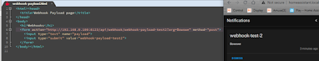
Of course I want to use webhook URLs in a webpage so I coded a form to send an input text box named payload.  In this case the item containing the information is trigger.data.payload.  Rather than sending an input text field I can add one or parameters to the webhook URL containing directives for HA.  I added a parameter called arg to the webhook URL and could access it in a HA template as trigger.query.arg.  The example below shows both the form item payload and the URL arg being sent from a webpage.  The URL arg is displayed as a HA notification whilst the payload is sent to Google Nest mini to be read aloud.


Implementation


This is great, I can add a variety of fixed and variable information from a web page into a HA webhook automation.
My first implementation is an automation which carries out the same functions as the buttons on the Lily Remote Control to implement volume control and display LED patterns on my programmable LED display.  It is very quick and simple to set this up, only about 15 minutes from concept to testing.