Background
Back in mid-May I disconnected the Ardino Mega from BEN2 and subsequently I didn't have any process to update BEN2 ROM. This meant that I was totally dependent on the existing ROM monitor program at address $8000 (called xmodem-2-shell-1 or mon2 for short) for loading any code I wanted to test or run.
In mid-June I successfully implemented a program (write-romx) which enables me to write code into ROM. This gave me the potential capability to upgrade the ROM monitor code. (to lib-3-mon or mon3 for short).
Copy mon2
I made a copy of the mon2 source program to form the basis for the new monitor. The aim was to make sure it worked in RAM then load it into ROM. Unfortunately, for reasons I didn't understand at the time, the copy didn't work. It appeared to download correctly but then wouldnt run.
As is usual in these circumstances, my approach is to cut down the program until I have at least a small part that is working. Eventually I cut the monitor down so that it just displayed a menu. The code was only about 300 bytes.
Create a symbol table
I started to embark on work to add functionality / subroutines gradually.
However I had a little flash of inspiration. I realised that all the subroutines I needed were already part of mon2 and resided in ROM. For example, the subroutine to display a menu is called cmdline_menu and looking at the link-map for mon2 I can see that it can be found in ROM starting at address $815A.
So all I need to do is replace my subroutine names with suitable ROM addresses and I can implement functionality with almost no extra code.
In fact, what I doing here is using mon2 code as a library. This is similar to what was done on old home computers. The vendors would, if you were lucky, would give you a list of ROM addresses for various functions you might want to use and you could then use them in your programs.
When I implemented libraries for my previous 6502 boards I ran into big problems with change control. It was very easy to not update addresses when a routine moved to a different location and took much work to maintain a (somewhat flaky) list. For this system to suceed I needed a better approach.
What I need is a symbol table showing subroutine names and their associated ROM addresses. As I will only update ROM occasionally, when a new version of the monitor is released, this table wont change frequently. The first change will occur when I cutover to a new monitor version.
My programming environment is now on WSL and I can easily access the ld65 link map which is created during the assembly - link procedure.
Using nifty linux tools like sed, awk, cut and column it didn't take long to process the link map, extracting all lines containing labels and their associated addresses. Some of these addresses are for branch statements but it doesn't matter as long as I have all the subroutine names. I could remove them manually, but so far I haven't needed to.
Once I have the labels I can format them and create a header file which I can use in my assembly programs. In the snippet below you can see that I have added a prefix "LIB" to the subroutine names.
For example within mon2 in ROM the subroutine which displays a newline on the terminal is term_newline and it resides in the monitor at location $852B
If I want to use this ROM routine in my program I simply include the header file symbol_table.h and use "jsr LIBterm_newline".
If I want to I can incorporate the code within my program by copying the source in and issuing "jsr term_newline".
Generally, I want to use "LIB" subroutines unless I new an updated version of a routine, either for extra functionality or error correction.
Create a small mon3
Rather than add all the functions I implement into the monitor I aim to keep it compact.
Initially I have restricted myself to m (memory dump), s(call subroutine), x(xmodem download), p(clear memory range) and I have added an extra function z which I use when testing a new monitor version, it exits the RAM test monitor and returns control to the ROM version.
Other options which I dont think are vital were removed: c (clear screen), j(jump to address),l(sticky key), o(blink LED), r(reset)
All the functions I am using (m,s,x,p) were already in mon2 so it is easy to add them to mon3, mainly a question of using the LIB version of subroutines. The assembly download procedure for mon3 is setup to download it to $3000. Typically the programs I download will reside at $1000 and the write-romx program will work at $2000 so I aim to avoid mixups over memory.
The addition of a z option is very important as it allows exit from the test monitor to the ROM monitor. The terminal prompt was changed from '>' in mon2 to '$' in mon3 so you can always tell which version you are using.
Also I removed the stack initialisation code from mon3 for a couple of reasons.
Firstly, although stack initialisation allows us to check how the stack has built up and what it contains more easily, I never use this functionality. Secondly if I initialise the stack within mon3 I cant issue a RTS opcode to return to mon2 as I have overwritten the stack entry containing a return address. I dont forsee a need to put stack initialisation back.
Update ROM monitor
Once I was happy that the monitor was working in RAM I wanted to check that I could save it in ROM and use it to start up my system.
I connected the ROM Output Enable and Write Enable wires to the VIA chip to facilitate update of ROM contents and ran my write-romx script to assemble and download mon3 to RAM and ran write-romx to copy mon3 to ROM at $9000.
The results were underwhelming. The program did not run properly at $9000 and I wasted some time mindlessly tinkering with scripts and download program changes.
I knew that mon3 was about 400 bytes long and worked when loaded at $3000 in RAM. I looked at memory locations to compare this with the version loaded at $9000 in ROM. I saw that the new code was 12 bytes longer!
For writing to ROM we download write-romx (about 120 bytes) to $2000 and mon3 code follows on immediately after write-romx in RAM. I checked this code and found that it was also 12 bytes longer than the original, indicating that 12 bytes had been added during download.
As my download package (write-romx + mon3) was just over $200 bytes I guessed, correctly, that the error was caused by my program not working with bigger downloads.
I managed to cut out some more bytes from the mon3 executable to make the total download package less than $200 bytes.
When I tried the download + copy-to-ROM again, I found that the executable was the correct size and tmon3 ran correctly in ROM.
This is great, we now have a new working monitor in ROM😀😀😀
The process of putting mon3 in ROM has a number of very rough edges but this represents a good step forward.
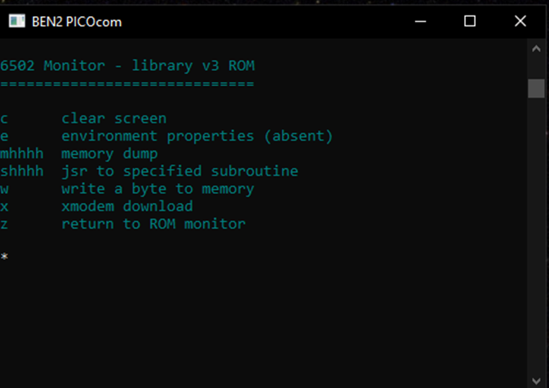
Another glitch I found, which can be seen on the screenshot above is that the monitor menu isn't properly displayed. I discovered this was due to a $00 byte erroneously inserted in ROM at address $9100. It is another error to be resolved before the monitor is finally implemented.
Although we are not ready to cutover to the new monitor I did a quick test cutover.
I removed the ROM chip from BEN2 and inserted it in the EEPROM programmer.
I then changed the reset vector in $FFFC and $FFFD, using the xgpro software, from $8000 to $9000.
I reinserted the chip in BEN2, powered up and reset the computer and my new monitor appeared😀
I then reset the ROM since mon3 is not yet ready for "production" use.
Fix programs larger than 512 bytes
I needed to work out why programs longer than 512 bytes ($200) would not load properly.
I wrote a test program to display text on the screen on the basis that it is easier to make a program bigger by adding text than it is by writing code. Also printing out a block of text will reveal missing / incorrect characters easily.
My previous text display subroutine could only show 255 bytes so I amended it to be able print larger blocks of text.
Rather than inserting newline codes in my text I amended the subroutine so that a tilde character '~' in the text indicates a newline. The display subroutine replaces it with a newline ($0A, $0D).
I found that as soon as my test program executable was more than 512 bytes long, these extra bytes were added and caused the program to mis behave.
I noticed that the extra characters were printable, and in fact they read "Minicom2.7.1". Clearly my terminal emulation program, which is conveniently left running during a download, inserts these characters. I realised that this is the Answerback message that minicom must insert when it receives an ENQ ($05) character. I looked at the hex values for the program I was downloading but there was no $05 value there. With a small flash of inspiration I realised that my xmodem download sends data in 128 byte blocks the download goes wrong near the start of the
fifth block after 512 bytes have been sent. The xmodem protocol specifies that a block number, in this case $05, is inserted in the header for each block, thus causing the error.
I looked to see if I could surpress the answerback in minicom but I could see no way. I considered reverting to my previous download method, using putty where I pause a session, complete a download and restart the session; I considered this to be a pain, I have got used to the easier method minicom provides.
Next I tried out PICOcom, which promises to be a basic emulator, based on minicom, but with fewer features. It works a treat, there is no answerback and my downloads are a lot more reliable😀😀
I was very pleased to be able to fix the problem without programming work.
Change individual ROM bytes
My write-romx program works by being downloaded to RAM with a header and payload immediately following it. It copies the payload to ROM as specified in the header.
It occured to me that the payload could be one or two bytes long and I could use a script to put the bytes into the payload.
The format required for write-romx is:
<write-romx load address> <write-romx binary> <payload load address> <payload length> <payload>
The example below shows a two byte payload (the value “$9000”) loaded to address $FFFC, $FFFD
Thus I now have an easy way of changing the reset vector, without having to put the ROM chip in the EEPROM programmer.
Although I now have a good method for updating the ROM monitor and changing the reset vector to use a new monitor, there is always a possiblity for me to screw up. If I change the reset vector incorrectly or the xmodem download subroutine isn't working my system is totally broken.
To safeguard my environment I made a ROM backup to another ROM chip using my EEPROM writer and xgpro software.
An irritating glitch
I mentioned earlier in this post that a single byte at address $9100 was missing from my copy. Obviously this would be disastrous if it happened again. I did some in depth investigation to clarify what was happening.
The error doesn't occur when copying to ROM, only to RAM.
The existing byte at the problem location remains unchanged (i.e. the copy program isn't inserting a duff value).
There is a single byte which isn't copied even if the program is 1k in size.
The error doesn't occur at all load addresses:
$9000, $9100, $9200, $A000, $A200, $A100, $9040, $9080 all have an error after 256 ($100) bytes
$9001, $9203, $A001, $9010, $9020 dont have an error.
Sadly I will need to use a workaround:
When I update my monitor program I will use a load address of $9001 or $A001.
I can then change the reset vector to $9001 or $A001 to use the new monitor by default.
Concluding Notes
In my last blog post I described the method to load a program into ROM. At the time I thought that I would soon be able to complete the monitor upgrade. A few problems have set me back so this post has had to concentrate on sorting them out. I am now confident that I am ready to update the monitor content and my next post will finish with monitor version 3 in use on BEN2.