Once I was happy with the design and layout of my new 6502 "Ben Eater" board it was time to build and test it.
Tools
An advantage of soldering a board is that I am unlikely to suffer from bad connection problems. The downside is that soldering errors are harder to correct. It makes sense to build the board in small stages, regularly checking functionality as the build progresses. My soldering ability isn't great and I felt it would be good to change my "make do" tools for better ones. I purchased: a soldering iron with a finer tip and more / adjustable power; wire strippers and cutters suggested by Ben Eater and a circular LED craft light to provide clearer more even illumination of the workpiece. I also purchased an SMD tester, not because I ever expect to solder SMDs but it is extremely useful as a circuit tester. Using the SMD tester I can quickly check that there are no shorts between adjacent tracks on the strip board - a common source of problems.

Solder memory
The first component to solder was the ZIF ROM holder and adjacent header pins. I attached the mega to the header pins on the side of the ROM holder and provided a sketch which read in the first 512 bytes of ROM data and displayed it.
Next I soldered the RAM holder and headers. Since ROM and RAM have the same pin out I could insert my ROM chip in the RAM holder, attach the mega to the RAM header and run the same sketch to test the RAM soldering.
Next I added the wires connecting ROM and RAM holders. The address (15) and data (8) pins on ROM and RAM are connected to each other forming busses. This meant that I could attach the mega to the RAM header pins, which is is long-term position and put the ROM in its holder. The remaining 5 pins (5V, GND, /WE, /OE and /CE) were then plugged into the mega at 5V or GND and my test mega sketch was able to read ROM data on the adjacent chip holder.
Step 4 was to add power connections. There are approximate rails down the middle of the board with some posts attached for external offoard power inputs and outputs. Power connections to chips on the board were connected to these rails or other components in a pragmatic way. I completed all power connects for the board at this time. I also added some clock signals and posts.
ROM testing
The final set of connections on the top row are for the NAND chip which provides control signals for ROM and RAM. I amended my ROM test sketch to provide the NAND inputs which are made available on the extended RAM header and control the ROM. Unfortunately the sketch did not work and I spent a long time searching for a solution to the problem. I became extremely agitated and took a break over Christmas and through January before trying again in mid-February. At last I found that the pinouts for the NAND chip I am using (4011CD) are slightly different from the 74HC00 in Bens circuit. This meant that I was wiring together outputs from two NAND gates, giving indeterminate results. Once I had diagnosed the problem it was easy to rectify my solder connections and I successfully tested reading and writing the ROM.
RAM testing
The last component which needed testing in the top half of the circuit was the RAM memory. I wrote a sketch to test the RAM but again, unfortunately it didnt work. To make sure I was trying to read/write RAM correctly I setup a RAM chip on breadboard and tested a standalone sketch.
When the sketch still didn't work I realised I had a duff RAM chip. I swapped it out and my standalone test sketch worked fine. About three out of ten of my RAM chips have been fault and a couple of others had bad pins. They were very cheap and I reckon they may be second-hand, removed from an old board. With a working RAM chip I was easily able to adapt my standalone sketch to work on the BEN2 board and I now have sketches which can easily test ROM, RAM and NAND.
The top half of the board comprising ROM, RAM and their NAND control logic is in working order at long last and I can start soldering connections to the bottom half of the board. It has taken vastly longer than anticipated but I hope that the solution will be more reliable than previous attempts.
CPU
CPU memory control lines have previously been soldered. The next step is to solder address and data bus wires to the CPU. The board is beginning to be quite crowded / full but it isn't too tricky to access the wires. The diagram below shows ROM+RAM+Power connections in blue and the extra connections for address and data bus in yellow.

Previously we have been concerned with testing ROM and RAM which was done rather differently from Ben Eaters original tutorials. We had extra testing sketches to diagnose / check that memory was working. Now we are more aligned with Ben's "Hello World" tutorial and I use the monitor sketch (adjusted for GPIO pins I am using) to check CPU initialisation.
When the Reset button is pressed the 65C02 spends 6 clock cycles then loads a reset vector from addresses $FFFC-$FFFD. It then starts loading and executing instructions from the address specified in the reset vector. In the test ROM I am using the reset vector is set to $8000. Starting the 65C02 this is what we see on the monitor:

A simplified view of memory is:
$8000 08$8001 ff
$8002 9a
$8003 a9
......
$FFFC 00
$FFFD 80
This demonstrates that the CPU is connected to address and data busses and its initialisation sequence works.
VIA
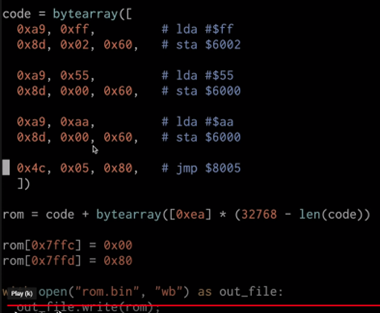
Finally we need to have a peripheral so that we can SEE our 6502 is able to DO something. I soldered the final board wires It is traditional to use an LED for this purpose. I referred back to Ben's tutorial video 2 which demonstrates a simple 6502 machine code program which uses VIA output pins to flash an LED. The program only comprises 18 bytes of code so it was simple to modify my write-byte sketch to write 18 bytes.
Conclusion
The flashing light is a suitable finale for the time spent building this hardware board. Until the board does something you can see it is just some chips and wires. A blinking LED is a traditional electronics "Hello World" objective with the associated satisfaction in demonstrating some mastery of the hardware/subject.
In retrospect it has been much more difficult than I anticipated to design and consturct my own layout for a Ben Eater board. When following the Ben Eater tutorials in February 2021 I reached the end of video 2 within a week and successfully flashed my light. However I feel I have achieved something of my own and I hope I will be able to progress smoothly through the next stages of the project.
Schematic, Layout and Board


No comments:
Post a Comment