Showing posts with label 6502. Show all posts

Thursday, 9 November 2023

6502 : BEN2 : MON5 cutover


Scope

The MON5 update contains no new functionality.  It comprises some hardware changes which seemed very straightforward but have required some hard work.

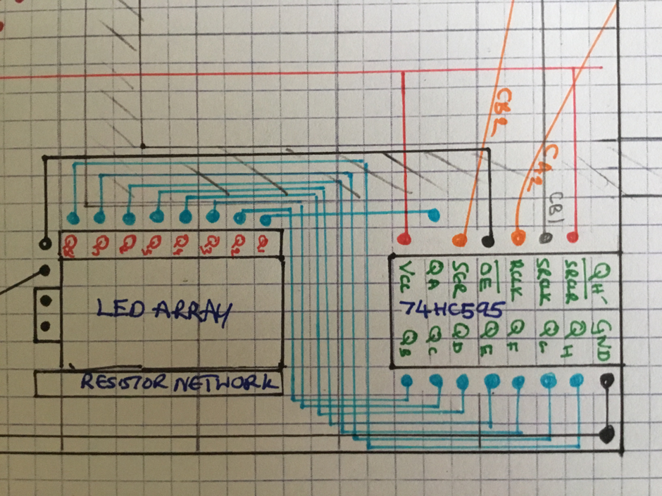
  • Add an LED indicator on the shift register display when interrupts are enabled.
  • Update the "write-byte" option to use PB1, PB0 to control ROM write enable.
  • Update the write-romx monitor download/upgrade program to use PB1, PB0
  • Update music program to use PB2 instead of PA1
  • Move breadboard components for shift registers/LEDs and sound to soldered AMI board.
  • Amend individual bits in VIA registers rather than overwriting complete contents

Change pins used for write-byte menu option

One minor change in MON4 was converting HD44780 LCD to 4-wire control, which freed up 4 VIA pins PB0-PB3.  Within MON4 I was aware that it was dangerous to share PA4 and PA3 between LED display and ROM-write functions.  My work-around was to only connect PA4,3 when required to update ROM code.
With the extra pins now available I decided to use PB1,0 instead of PA4,3 to control ROM writing.  PB1,0 will not be used for other functions which makes it safe to leave wires connected all the time.  Previously PA4, PA3 attached LEDs provided handy indicators to show write-ROM operations so I also need to set up an LEDbar LED to indicate that ROM is being written. 

Previously when writing to VIA CONFIGA/B and PORTA/B registers I have simply written an 8-bit value over-writing existing contents.  It is preferable to only update the specific register bits required for a specific operation, to avoid unwanted side effects.  The registers can be read as well as written and individual bits can be updated using appropriate AND, OR, EOR operations before writing back the updated values.

For extra security I decided to leave PB1, PB0 as inputs unless a write-ROM operation is in progress, this helps prevents accidently writing values to those pins.
Now that PA4 and PA3 are not connected to write-ROM pins (ROM/WE and ROM/OE) it is actually safe to leave the code which updates them in place.  I do this so that we can actually load code by reconnecting those wires if necessary and we have an extra visual indication that write-ROM is taking place.

The menu option " write ROM" requires code to be copied from ROM to RAM, then executed in RAM whilst the ROM is unavailable (for reading instruction) during the writing process.  For the copying process to work, there must be no absolute addresses in the "RAM code", which means there must be no subroutine calls.  I had a clever idea that I could incorporate a subroutine, providing it was copied to RAM with the other code. It was a bad decision.

Change write-romx download program

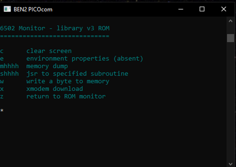
Back in July as part of MON2 I developed a program write-romx which uses xmodem to download a program to RAM and then copies it to ROM.  It was an excellent innovation and allowed me to finally detach the Arduino Mega "umbilical cord" I was previously using.
It works fine and hasn't needed updating since then.  I now need a new version to use PB1, PB0.  Although it is a standalone program some of the system subroutines it uses, together with the shared memory map have been updated since it was written, and I should carry out a general update.

Unfortunately I underestimated the pitfalls of this task and rushed into a quick implementation.  Sadly, when the new version I was testing went wrong it over-wrote crucial parts of the ROM and made BEN2 unusable.😢
I had a backup ROM chip with the MON2 image loaded so I was able to update a copy of the MON2 ROM to MON3 and then to MON4.  After wasting a couple of days I was back on track.
I then proceeded very carefully to make changes to write-romx, testing each small change I made.  I found that the local subroutines with the RAM copy program were a very bad idea - I overlooked some detail (perhaps with the JSR mechanism) which stops them working.
Somewhat chastened and a little bit wiser, and at a slow but steady pace, I successfully updated write-romx.

Board Update

By the time MON4 was complete I had a breadboard hanging off the computer containing a shift register and LED together with a speaker connection.
When I created the AMI daughter board, there was some unused space and it was always my intention to add new hardware to AMI when appropriate.
Despite putting a lot of effort into making it easy to detach the board I was nervous about doing so.  At worst failure would mean BEN2 could never be resurrected.
I carefully noted connections as I removed them from AMI, until AMI could be dismounted from its stand was available for me to solder.
My soldering is improving and I was very careful to position the connections carefully as I worked.  On completion I checked the board for shorts between adjacent tracks and continuity tested all the connections.
Reconnecting AMI I was very pleased to see that BEN2 was still working and, after some minor tweaks the new shift-register/LED-bar and sound were working as well.
I dont know whether this is the final version of the BEN2 hardware but it must be close.

Documentation Update

A major part of the cutover work was bringing the schematic and board layouts up to date.  One would normally expect to update these before doing the work, but as the changes developed gradually I could add them in easily enough.  I will add the latest diagrams to this blog - I almost think they are artistic.


Friday, 20 October 2023

6502 : BEN2 : MON4 cutover

It was back in July when I last updated the monitor program which starts when the 6502 is booted. MON3 has proved to be very reliable, it has allowed me to forget about the details of downloading to RAM since it rarely goes wrong.  Restarting BEN2 also goes smoothly most of the time so I can concentrate on new developments.

New Functionality

Since then I have focussed mainly on adding VIA functions to the system. I started off with all 16 VIA pins on ports A and B in use: PA0-PA1 are wired for buttons, PA2-PA4 are LEDs, PA5-PA7 and PB0-PB7 are used for the LCD display. The first enhancement was to add a 74HC595 shift register, as described by Garth Wilson which uses only three pins, CA2, CB1, CB2 all of which are available.  It provides me with 8 extra pins and allows me to add an 8 LED bar (or 8 LEDs)  I can easily chain further shift registers if I need more output pins.


Next I followed Ben's advice on VIA interrupt functions; an Interrupt Service Routine and Interrupt Vector were initially set up to process a button interrupt on CA1.  At this stage I don't have anything specific which requires a button, so the ISR simply displays a letter on the screen.

VIA chips also provide two timers; I followed Ben’s tutorial to add a timer interrupt. Each 10ms timer  interrupt causes the ISR to increment a clock tick.  Using 100 ticks I can display a clock which increments each second.  I can also schedule regular events such as an LED flashing in the background.
To facilitate background activities we minimise code in the ISR and add an idle loop to the monitor which constitutes a simple state machine.  Whenever the monitor (or VIAtest) is waiting at the menu there is a check on the current tick count to determine whether other activities such as the LCD clock display or an LED flasher need updating.

The final major investigation was to add sound by setting up a buzzer.  It is a very easy addition, simply toggling an output pin with a speaker attached many times a second to generate a sound.  This exceeded expectations, the sounds are good and I can control VIA output to generate sounds of varying pitch.  This allowed me to play different notes, scales or tunes on BEN2, culminating in a rendition of three blind mice.

I still have a shortage of VIA pins so I changed over the LCD instructions from 8-pin to 4-pin.  The updates are quite straightforward.  Changing from 8-bit to 4-bit operation was a problem until I found it requires a magical reset sequence .  PB0-PB3 have now been freed up for other purposes.
At this stage I decided that I have plenty, maybe too many, changes for the current release and that I should leave hardware updates to the next release.

System Updates

Most of these changes don’t affect the monitor program itself, they provide extra or updated versions of subroutines used by other programs.  Since I bundle all ancillary subroutines with the monitor when I save it to ROM I can release them all together.  The monitor does need to be updated to include an ISR and to allow other processing to be carried out whilst waiting for user input.  It also includes a couple of extra menu options.  The “write byte” option has been added to update a single byte of ROM or RAM and I added an option to turn off interrupts when not required.

MON3 is stored at $A001 in ROM so I can save MON4 at $8001 and test in parallel, without destroying the ability to use MON3.

1 The write byte option has already been incorporated in the RAM development version of MON4 so I could write MON4 to ROM and I verified that it continued to work as expected.

2 I added the Interrupt Service Routine to MON4 at $8004 and set the reset vector at $FFFE-$FFFF to $8004 using "write_byte".  MON3 didn't use interrupts so this change didn't affect its operation.

3 I  have started to use Dirk Grappendorfs macros to save and restore A, X, Y registers on entry / exit to subroutines.  There is a convenient macro to load a 16-bit memory pointer.

4 I tried to rationalise zero page memory variables / usage.  I now have three 16-bit registers R0,R2 and R4 or alternatively six 8-bit registers R0, R1, R2, R3, R4, R5.  I setup local names within subroutines which can rename these page zero "registers" to be more meaningful in particular contexts.

5 Tests to terminal and shared routines were quite straightforward.  The main one was to add Binary Coded Decimal (BCD) conversion to SHARE.  BCD converts a binary number to a decimal one; Ben dedicated a whole video to setting it up so I expect to to be useful.

6 I added the button and timer interrupt routines to MON4, these are specific to the ISR so I keep them local to MON4.s rather than adding to shared routines.
Once I added interrupt processing other options (s-subroutine jump, x-xmodem download) stopped working  so I make sure that interrupts are turned off before moving to other programs.  

7 I added VIAtest subroutines for shift register processing to VIA.s

8 I added VIA Sound subroutines to VIA.s so that any program can play buzzers / musical notes.

9 I changed LCD operation over from 8-bit mode to 4-bit mode.

Once all functionality has been added I could change the reset vector from $A001 (MON3) to $8001 for MON4 using Write Byte.  We now have a new monitor.

Endnote

MON4 is another big step forward for my BEN2 6502 system.  Extra ports, interrupts, timers and sound are all significant useful additions.  The software changes are quite major and I aim to catch up with related hardware changes on the next release.  


Monday, 2 October 2023

6502 : BEN2 : Sound

Theory

We already have a variety of uses for the 65C22 Versatile Interface Adapter outputs: LED, LCD, Shift Register/LED bar, interrupts/clock ticks.  We haven't previously provided any sound output and I was attracted to a brief article "Add sound to your 6502 for 10 cents and a speaker".
The article explains that all you have to do is connect a small 8 Ohm, 1 Watt speaker to VIA output pin PB7 in series with a 47uF capacitor and a 100 Ohm resistor.  You can then generate a square wave output from the VIA which translates to a sound of the corresponding frequency on the speaker.

Proof of Concept

 I don't have PB7 free at present so I will have to generate the wave form myself. I have recently attached a 74HC595 shift register (SR) to the VIA to provide extra outputs so I can easily use one of those outputs.

It occurred to me that my clock timer generates interrupts at 10ms intervals.  If I toggle an SR output in the interrupt service routine I generate a square wave output with period 20ms which will give me an output frequency of 1000/20  = 50 Hz.  This is the same frequency as mains hum so I should hear a low buzz from the speaker.

I connected up a little buzzer I had available (from my kit of 37, mainly useless, arduino peripherals) to a resistor, capacitor and SR output 0.  I added a couple of instructions to my interrupt service routine to toggle SR0 each time an interrupt is generated.  The test worked first time and I was able to hear a, rather quiet, low buzzing sound.  😀😀😀


The sound pitch is rather low for my liking, it is determined by the rate at which the timer generates interrupts.  If I decrease the period between interrupts, for example so that the period is 1ms, the pitch increases from 50Hz to 500Hz which is a lot better, it sounds approximately like middle C.  However an interrupt each millisecond only leaves 1000 cycles between interrupts for all interrupt processing, which may be limiting.

One positive aspect of using the ISR for sound generation is that programs can continue with other tasks whilst the sound continues.

For the next investigation I will setup sound as a general purpose subroutine which any program can call to leave a beep, buzz or ping.

Volume

The sound of the speaker is masked by other sounds in the room.  Although I dont want loud irritating sounds coming out of the buzzer I would like it to be somewhat more noticeable.  I tried two other speakers attached to the 6502, a 5cm 8 Ohm 1 Watt and a 1CM 8 Ohm, 0.5 watts.  The 5cm speaker was a bit louder and the 1cm speaker was quieter.

I also tried changing the 100 Ohm resistor value.  All three options were somewhat louder when there was no resistor in series.

I have a little PAM8403 5v, 3W+3W stereo amplifier, which I felt might resolve my issue.  It sometimes worked and made the sound louder and sometimes produced crackles.  I think the input voltage/current was too high causing it to mis-function.  I also tried to add a volume control to the amplifier input but it didn't seem to make a difference.  

It occured to me that if I need a small gain, of say 5, I should be able to make a simple transistor circuit to function as an amplifier, but I didn't feel like diverting myself to "analog" work.

It also occured to me that the shift register may not provide as much current output as the VIA so I changed my program to output to IVA pin PA1, which has a button attached.  The sound was a bit louder again so the VIA does provide a more power.

I believe I could get the amplifier working if I look into the hardware capabilities and voltage/currents in the circuit.  However, I decided, for the moment to stick with my 5cm speaker with no in-series resister and to utilise VIA output.  This combination provides an acceptable volume without making the system more complicated.

Sound Subroutine

 The sounds subroutine is simple.  An inner loop (lines 178-186 in the example below) is executed to toggle an LED bit.  A delay (mid_delay in the example below) is added into the loop to alter the sound frequency; a larger delay causes a lower frequency, no delay leads to the highest pitch.  The x register controls how many times the loop is executed, ie how long the sound is output for.


The sounds subroutine can be called with different values of A-reg for frequency and X-reg for duration.

At this stage I realised that higher notes sound quite musical so I may well be able to play simple tunes on the computer.

Tuning

It is common to denote musical notes in 8 octaves, each containing 8 notes.  Middle C is C4 and notes going upwards are C4, C#4, D4,D#4,E4,F4,F#4, G4, G#4, A4, A#4, B4, C5... This is slightly confusing.  Each octave has 12 notes, the 8 "white keys" and 5 sharp (#) "black keys" on the piano.
If music is played in the key of C major it doesn't need any sharps, other keys require sharps to make them sound right.
 The pitch (frequencies) of musical notes are related mathematically with the reference note being A4 (440Hz), If we can determine the parameters for one note (middle C, in my case) we can calculate appropriate values for other notes.

I found a convenient piano program webpage which allowed me to play notes.  I started by adjusting the A-reg value in my sounds subroutine until one sounded pretty much like middle C, I then calculated the frequencies and corresponding A-reg values for other notes.
Higher notes take less time to play so I also had to calculate durations for the X-reg values so that notes are all the same length.
This gave me a table of values for A-reg FREQUENCY and X-reg DURATION.  I added these a symbols in my program so that I can play notes easily.


Note Lengths

I can now play a sequence of notes and we have the beginnings of a tune.  The notes I chose were E4, D4, C4 which happen to be the first three notes of "three blind mice", and this has become my mission, to be able to play the nursery rhyme out of the computer speaker.

Notes have different lengths.  Having set up the durations shown above I judged that the shortest note that I can play is a semi-quaver which represents once round a loop.  Quavers, crotchets minims, ... require 2, 4, 8 iterations.

The notes sound a bit strange as there is no gap between them.  If you were pressing piano keys there would be a short lull between notes so I needed to add a gap.  I did this by making a delay based on 1/8th of each note, so a shorter note has a smaller gap after it.

I also tidied up my testing code a bit and renamed my subroutine from sounds to note as we are not playing a buzzer anymore we are playing music!

Three Blind Mice

We are now ready to play a tune.  I setup the notes as frequency, duration, length triplets in memory and provided a loop to load each triplet and play the corresponding note.  It actually sounds ok. 😀😀😀


End Note

This is excellent.  I started out wanting a simple buzzer and I have ended up with the ability to play nursery rhymes.  I have another type of output available.  It could be very useful during debugging as it is independent ot screen or LCD output.


Monday, 7 August 2023

6502 : BEN2 : Clock Timer

Basic timer

In addition to hardware interrupts the VIA (Versatile Interface Adapter) provides two timers which can generate interrupts and Ben Eater has a very good tutorial which explains their use.  In the first example a one shot timer counts down to 0 then sets a bit in the IFR (Interrupt Flag Register).  The counter is a 16-bit register and is decremented each clock pulse so the maximum count down is 65535, approximately 65mS.  If we toggle an LED and restart the counter each time the interrupt occurs we have an LED flashing at about 10Hz.

As you can see from the code below, a loop via_delay is used to check whether the IFR flag has been set by the counter.  Clearly it isn't very useful to sit in a loop waiting for a flag to be set although you could add more code to do other functions within that loop.


Tick Timer

Ben's second example shows a very good clock feature which we will be able to use regularly.  The timer is put into freerun mode so that it starts again as soon as it reaches zero.  In addition to setting the IFR a 6502 interrupt is generated.  The interrupt service routine (ISR) is invoked on the 6502 each time the counter hits zero, and simply updates a four-byte tick counter in zeropage memory.

The counter is setup to hit zero every 10ms so, if we want to toggle an LED every second, we simply check whether the tick counter has increased by 100.  The following program shows the various parts of the tick timer.  On startup init_timer is executed to zero the tick counter and the timer is set to $207e giving 10mS interrupts.  Irqvia is at a fixed address $1003 and is invoked to increase the tick count each time a timer interrupt occurs.  For this demo there is a loop which updates LED and LCD periodically.


Clock program

My VIAtest program is used to check out all the VIA functions so I need to add the timer function in.  As the VIA button interrupt, LED shift register and timer each use a selection of ACR (Auxiliary Control Register), PCR (Peripheral control register) and IER (Interrupt enable register) I first disabled the button and shift register temporarily.  I copied across the timer initialisatio routine and ISR (Interrupt Service Routine) code easily.  With these in place the tick count was automatically incremented, although it wasn't in use.

VIAtest displays a menu and waits for the user to enter a character to choose a function such as displaying an LCD message or turning on an LED.  I amended the program so that it checks to see whether a character has been entered rather using term_getc to wait for a character.  If no character has been entered, other routines are called to see whether the LCD or LED needs updating based on the tick count.  In fact this is a simple state machine which multi-tasks by looping round a number of functions.

To enable the shift register and button, I had to check the VIA initialisation routine carefully and ensure that all bits were set correctly.  The button and LED bar then worked as normal.

The LCD clock display was straightforward to setup.  I added some variables clock_time, hours, minutes and seconds to my zeropage variable list and arranged for the seconds counter to be incremented after 100 ticks.  As each tick is 10mS this gives me an update every second.  Minutes and hours variables were incremented after 60 seconds or 60 minutes were reached.
I could then display the time using the three variables as hh:mm:ss on the LCD.
The update works independently of other VIA test functions.


Saturday, 5 August 2023

6502 : BEN2 : Interruptions

Buttons

Ben Eater included a number of buttons in his original board specification.  I installed a couple of buttons on BEN2's daughter board AMI but haven't found a reason to make use of them yet.  Buttons are the most basic input method for a DIY computer and potentially you could be stuck with button input and LED or LCD output.  Thankfully by adding the ACIA I have the ability to keyboard / terminal input / output making buttons unnecessary.
However, a button can be very useful as an interrupt mechanism.  For example, my simple blinking LED test cant easily be terminated.  It would be good to be able to leave the LED blinking until a button is pressed to stop it.

Bens tutorials

Ben provides a couple of tutorials, "interrupts" and "interrupt handling basics" to familiarise use with their use.  The first one describes 6502 IRQB and NMIB pins which implement controllable and non-maskable interrupts respectively.  IRQB interrupts assume that the device at the other end should clear the interrupt situation; it has a tendency to report a lot (hundreds and thousands) of interrupts.  In fact Ben's "binary converting to decimal" (BCD) routine is very useful to count them.  Non-maskable interrupts are very dangerous as they can interrupt absolutely any code, including interrupt service routines or themselves, so they are rarely appropriate.
Ben's second video describes how the W65C22 VIA provides an enhanced interrupt capability and shows how to to set it up, so that was the one I implemented.

Hardware connections

The VIA has two pins CA1 and CA2 which can be setup for interrupts.  As I previously used CA2 for my shift register I used CA1.
I connected up a button with a pull-up resistor to the positive rail so that when the button is pressed the signal on CA1 changes from 5V to GND.
I also need VIA pin 21 (IRQB) connected to 6502 pin 4 (IRQB) but that was already in place in my original build for BEN2.

Reset Vector

The 6502 IRQ vector is fixed at memory address $FFFE-$FFFF.  I set the contents to be the address $1003.  This allows me to load my test programs at $1000 as usual and, by making the first instruction a "jmp start", the interrupt service routine will follow on immediately at $1003.

Test program

My test program was very simple.  At the start of the program I initialise the interrupt on CA1 by setting values in IER (Interrupt Enable Register) and PCR (Peripheral Control register)
Before that there is a simple call to a subroutine for interrupt handling (button_int) the subroutine below followed by a RTI (Return from Interrupt) opcode.


My interrupt handling routine was very basic, I just displayed a letter 'j' on the screen - very dull.
Still, this is a useful addition to my system.

Wednesday, 12 July 2023

6502 : BEN2 : VIA : We need more LEDs - use a shift register

Requirement

Most recent BEN2 activity has been focussed on creating a user-friendly development environment.
We used a couple of VIA pins for our ROM-writing program and that only leaves three VIA pins available for LEDs, buttons and other things.

Adding an extra VIA would require me to sort out addressing logic (chips and wiring) to reserve a new address range for the second VIA so it would create major upheaval.  A less extreme alternative would be to change my LCD logic from the 8 to the 4 pin version.  However that would only give me four extra lines.

I prefer an option described by Garth Wilson which utilises the shift register function built into the 6522 VIA.


Shift Registers

Shift registers are commonly used for serial to parallel (SIPO) and parallel to serial (PISO) conversion.
The diagram above shows 74HC595 shift registers being used for SIPO.  A stream of 8 bits is sent from the VIA chip to a 595.  The 595 then latches the 8 bits to its output lines which can have LEDs or other output devices attached.  We only need three VIA pins to send the data.  Even better we can daisy chain the 595s so that we have 8,16,24, 32,....outputs.

Shift register operation is quite straightforward, I learned a bit more from a random article for the Onion SBC which provided the schematic below.  Individual bits (on pin 14) are transmitted into the register, at each clock pulse ( on pin 11).  At an appropriate time they are latched (using pin 12)  to a "storage register" so that the output can be used.  For our purposes the VIA will organise a stream of 8 bits on the CB2 pin with a clock signal on CB1.  When the 8 bits are in the 595 SR we will set CA2 high to latch these to Storage Register Outputs. 

This seems a fine way to proceed so that we can add some LEDs, or other outputs and  I purchased some 74HC595 chips from ebay for £0.60 each.

I dont foresee much need for more inputs but I could use 74HC165 shift registers provide PISO conversion.  One application area which could utilise this solution would be dip switches, each of which requires a line.

Connections

A good tutorial from DroneBotWorkshop provides pinouts for 74HC595
I connected this to an LED array on a breadboard.  There are 8 LEDs in the array and each is connected to ground using a resister in the resistor network.  This is very quick and easy to setup.  8 output pins from the 595 connect to the positive side of the LEDs so that when a 595 line goes high the associated LED lights up.  The 6522 VIA provides "bits" using CB2 and CB1 and they are output to the LED array when CA2 goes high.

Programming


With the wiring in place, we need a BEN2 program which will cause the W65C22 VIA to send appropriate signals to the '595.  Garth Wilson provides some guidance on his web page.  We need to use three W65C22 registers
        Shift Register    (SR)
        Auxiliary Control Register (ACR)
        Peripheral Control register (PCR)

Firstly, using PCR we set CA2 low, so there is no output from the '595.

Next we configure the 6522 to use the 6502 system clock (PHI2) to pulse serial bits to '595 as shown in the 6522 datasheet timing manual


We are ready to go.  Each time an 8-bit value is loaded to the W65C22 shift register
it is sent to '595 and as soon as we pulse CA2 high the data is output to LEDs.
The code is shown below, there is an init subroutine and a display subroutine.  I put a short delay in the display subroutine so that 6502 waits for bits to be transferred before they are displayed.

Result

This was an enjoyable and rewarding days work.  I have expanded the output capabilities of the system, adding 8 LEDs with very little effort.  Even better I could daisy chain a number of 74HC595 chips to add as many as I want.

Tuesday, 4 July 2023

6502 : BEN2 : Monitor v3 finally released

Monitor v2

A couple of months ago, at the end of April, I attached an ACIA on a breadboard to BEN2 which gave me terminal access to the system.  Using the serial connection I was able to download programs from my PC to BEN2 using a simplified xmodem transfer.  In early May I setup monitor v2 which included xmodem file transfer and other basic functions such as memory display, jump subroutine and clear screen.  

For the reset of May I focussed on creating AMI, a daughter board for BEN2 "peripherals" comprising the ACIA, LCD, buttons, LEDs and clock.  By the end of this work I had a robust, soldered daughter board alongside BEN2, mounted on a perspex stand.  To make the system neat, pretty and more reliable I detached the Arduino Mega which I had previously been using to download programs.  This gave me a hardware setup which begins to look like a real computer.

Using xmodem, meant that I could download and run programs more quickly and easily to RAM.  I spent some time making the process more streamlined, quicker, easier, more predictable and making programs relocatable so that I could have multiple concurrent programs in RAM.

The downside of using xmodem and not having the Arduino attached was that I couldn't update ROM.  Luckily monitor v2 has proved very reliable and I have been using it without problems for the last couple of months.

I was reluctant to reconnect the Arduino Mega again to update ROM programs and my thoughts turned to how I could run a 6502 program on BEN2 to update its ROM.

Writing ROM

Ben Eaters 6502 design required the ROM to be removed for programming. BEN2 was setup specifically so that the ROM could be updated in situ using an Arduino Mega.  There are only a couple of extra hardware connections required to achieve this; specifically it was necessary to control ROM /WE and ROM /OE, the ROM write-enable and output enable pins from the Arduino.

After a little experimentation I developed a program write-romx, which runs in RAM and copies a program from RAM into ROM.  I set up write-romx so that I could download it from the PC with the program destined for ROM attached to the end of it.

I wrongly thought that I had nearly finished my work at this stage.  I had to change my terminal emulator to resolve an issue and tweak the timings to ensure bigger downloads were reliable.  I also found an irritating error, not yet resolved, which stopped me using various ROM load addresses.

In addition to writing programs to ROM, I need to be able to write individual bytes, for example reset vectors, and I developed a script, using write-romx, to do this easily.

Libraries

Once I had a basic method for writing to ROM, I started to work on a new monitor program.  Initially I could only write short programs and I realised I could use monitor-v2 subroutine in my new programs providing I knew their ROM addresses.  I developed a little shell script which analyses an assembly map and extracts address information to create a symbol table.  I arranged for the symbol table to be in the form of a header file, with all subroutine names prefixed with "LIB".  I could now use the monitor-v2 subroutines in any of my programs just by prefixing them with "LIB".  This kept my program code and download times much shorter.

My previous attempts at providing libraries were very frustrating as any errors in version or address of subroutines usually caused programs to fail and the update process was manual.

Programs

Now that I had a platform to develop / update programs for monitor-v3 I could put some effort into providing some extra functionality.  I decided I should focus providing a set of "driver" subroutines for VIA hardware and the terminal.

At present I am using the LCD screen and LEDs on VIA I/O ports.

There are quite a few capabilities within the HD44780 driver chip such as scrolling text, custom characters.  I decided I only want basic ones to control the LCD screen.  I made sure that I can clear the screen, display character output starting at any location on the screen, delete top or bottom row.  I wrote a test program VIAtest to test new and updated subroutines.

If I needed an existing subroutine within VIAtest I could use a monitor-2 LIB subroutine.
Some subroutines needed to be updated before use and I used a local version within the program, with the corrections / additions.

I only needed LED subroutines to turn the red, amber, green LED on or off.  I did provide a blink function but it is limited to a fixed duration as I don't have a "key pressed" interrupt or button capability to terminate blinking.

I developed TERMtest to provide extra terminal functions.  Various useful functions were added to:

  • write out a large block of text
  • position cursor at particular [row, column] position
  • change the colour for character display
  • erase screen and display menu


Building monitor-3

Monitor-3 started life as a minimal cutdown version of monitor-2 that I could fit into 512 bytes.  The minimal functions provided were m (memory dump), p (clear some memory), s (subroutine jump), x (xmodem download), z (return to monitor at next level).  It used monitor-2 library routines as far as possible.

There was a lot of work build monitor-3 ready for burning to ROM.

Firstly I took all monitor-2 subroutines (except any local ones) and copied them to three files depening on function TERM (terminal control), VIA (LED, LCD) and SHARE (utilities).  I added new subroutines from VIAtest and TERMtest into these files and replaced old versions with any that had been updated.  I also updated my symbol and zero page variable definition header file memory_map_v1 with extra symbols and zero page variable names for new and updated values from monitor-3, VIAtest and TERMtest.

Once I had tested monitor-3, VIAtest and TERMtest to make sure they still worked I sanitised the programs and include files to make sure they confirmed to some basic standards

  • Tab character at start of line before each opcode
  • Comments aligned consistently
  • Registers saved / restored in all subroutines - or reason for not doing so provided
  • "cheap" labels with local scope, beginning with "@", used in all subroutines

Thirdly I had to remove all "LIB" references in monitor-3, VIAtest, TERMtest to make sure that I have a consistent set of subroutines in monitor-3 and no dependencies on monitor-2 (which will be deleted soon).  This gave me three working programs using a set of tested subroutines, all of which were local to the program or in shared include files.  The programs were about 1kB-1.5KB in size. 

Finally I was ready to write the new monitor so I connected up my two ROM write wires and ran the write-romx program to save monitor-3 to $A001.
I saved a NOP code at $A000 (to circumvent my unresolved "lost byte" error) and changed the reset vector using a script to $A000.
I hit the reset button and saw...the monitor-3 menu 😀😀😀😀


I now have an updated monitor in ROM which forms a great basis for further development.

Concluding notes

The ability to develop programs easily in RAM and flash new monitor versions to ROM are great improvements.  My previous boards have all gone downhill as I added functions so it was important to me that I have a good environment to develop further ideas. 
Previously, the provision of the AMI daughter board was a big step forward making the hardware reliable.  Monitor-3 should provide a stable development environment, including the use of library subroutines and represents a similarly important step in making the software reliable.

In summary, this is wonderful because BEN2 is starting to feel like a (1980s) computer.

Sunday, 2 July 2023

6502 : BEN2 : Flashing an updated Monitor to ROM

Background

Back in mid-May I disconnected the Ardino Mega from BEN2 and subsequently I didn't have any process to update BEN2 ROM.  This meant that I was totally dependent on the existing ROM monitor program  at address $8000 (called xmodem-2-shell-1 or mon2 for short) for loading any code I wanted to test or run.  

In mid-June I successfully implemented a program (write-romx) which enables me to write code into ROM.  This gave me the potential capability to upgrade the ROM monitor code. (to lib-3-mon or mon3 for short).

Copy mon2

I made a copy of the mon2 source program to form the basis for the new monitor.  The aim was to make sure it worked in RAM then load it into ROM.  Unfortunately, for reasons I didn't understand at the time, the copy didn't work.  It appeared to download correctly but then wouldnt run.

As is usual in these circumstances, my approach is to cut down the program until I have at least a small part that is working.  Eventually I cut the monitor down so that it just displayed a menu.  The code was only about 300 bytes.

Create a symbol table

I started to embark on work to add functionality / subroutines gradually.

However I had a little flash of inspiration.  I realised that all the subroutines I needed were already part of mon2 and resided in ROM.  For example, the subroutine to display a menu is called cmdline_menu and looking at the link-map for mon2 I can see that it can be found in ROM starting at address $815A.
So all I need to do is replace my subroutine names with suitable ROM addresses and I can implement functionality with almost no extra code.

In fact, what I doing here is using mon2 code as a library.  This is similar to what was done on old home computers.  The vendors would, if you were lucky, would give you a list of ROM addresses for various functions you might want to use and you could then use them in your programs.

When I implemented libraries for my previous 6502 boards I ran into big problems with change control.  It was very easy to not update addresses when a routine moved to a different location and took much work to maintain a (somewhat flaky) list.  For this system to suceed I needed a better approach.

What I need is a symbol table showing subroutine names and their associated ROM addresses.  As I will only update ROM occasionally, when a new version of the monitor is released, this table wont change frequently.  The first change will occur when I cutover to a new monitor version.

My programming environment is now on WSL and I can easily access the ld65 link map which is created during the assembly - link procedure.
Using nifty linux tools like sed, awk, cut and column it didn't take long to process the link map, extracting all lines containing labels and their associated addresses.  Some of these addresses are for branch statements but it doesn't matter as long as I have all the subroutine names.  I could remove them manually, but so far I haven't needed to.

Once I have the labels I can format them and create a header file which I can use in my assembly programs.  In the snippet below you can see that I have added a prefix "LIB" to the subroutine names.

For example within mon2 in ROM the subroutine which displays a newline on the terminal is term_newline and it resides in the monitor at location $852B


If I want to use this ROM routine in my program I simply include the header file symbol_table.h and use "jsr LIBterm_newline".
If I want to I can incorporate the code within my program by copying the source in and issuing "jsr term_newline".
Generally, I want to use "LIB" subroutines unless I new an updated version of a routine, either for extra functionality or error correction.

Create a small mon3

Rather than add all the functions I implement into the monitor I aim to keep it compact.
Initially I have restricted myself to m (memory dump), s(call subroutine), x(xmodem download), p(clear memory range) and I have added an extra function z which I use when testing a new monitor version, it exits the RAM test monitor and returns control to the ROM version.
Other options which I dont think are vital were removed: c (clear screen), j(jump to address),l(sticky key), o(blink LED), r(reset)

All the functions I am using (m,s,x,p) were already in mon2 so it is easy to add them to mon3, mainly a question of using the LIB version of subroutines.  The assembly download procedure for mon3 is setup to download it to $3000.  Typically the programs I download will reside at $1000 and the write-romx program will work at $2000 so I aim to avoid mixups over memory.


The addition of a z option is very important as it allows exit from the test monitor to the ROM monitor.  The terminal prompt was changed from '>'  in mon2 to '$' in mon3 so you can always tell which version you are using.

Also I removed the stack initialisation code from mon3 for a couple of reasons.
Firstly, although stack initialisation allows us to check how the stack has built up and what it contains more easily, I never use this functionality.  Secondly if I initialise the stack within mon3 I cant issue a RTS opcode to return to mon2 as I have overwritten the stack entry containing a return address.  I dont forsee a need to put stack initialisation back.

Update ROM monitor

Once I was happy that the monitor was working in RAM I wanted to check that I could save it in ROM and use it to start up my system.
I connected the ROM Output Enable and Write Enable wires to the VIA chip to facilitate update of ROM contents and ran my write-romx script to assemble and download mon3 to RAM and ran write-romx to copy mon3 to ROM at $9000.
The results were underwhelming.  The program did not run properly at $9000 and I wasted some time mindlessly tinkering with scripts and download program changes.

I knew that mon3 was about 400 bytes long and worked when loaded at $3000 in RAM.  I looked at memory locations to compare this with the version loaded at $9000 in ROM.  I saw that the new code was 12 bytes longer!
For writing to ROM we download write-romx (about 120 bytes) to $2000 and mon3 code follows on immediately after write-romx in RAM.  I checked this code and found that it was also 12 bytes longer than the original, indicating that 12 bytes had been added during download.

As my download package (write-romx + mon3) was just over $200 bytes I guessed, correctly, that the error was caused by my program not working with bigger downloads.
I managed to cut out some more bytes from the mon3 executable to make the total download package less than $200 bytes.
When I tried the download + copy-to-ROM again, I found that the executable was the correct size and tmon3 ran correctly in ROM.


This is great, we now have a new working monitor in ROM😀😀😀
The process of putting mon3 in ROM has a number of very rough edges but this represents a good step forward.

Another glitch I found, which  can be seen on the screenshot above is that the monitor menu isn't properly displayed.  I discovered this was due to a $00 byte erroneously inserted in ROM at address $9100.  It is another error to be resolved before the monitor is finally implemented.

Although we are not ready to cutover to the new monitor I did a quick test cutover.
I removed the ROM chip from BEN2 and inserted it in the EEPROM programmer.
I then changed the reset vector in $FFFC and $FFFD, using the xgpro software, from $8000 to $9000.
I reinserted the chip in BEN2, powered up and reset the computer and my new monitor appeared😀
I then reset the ROM since mon3 is not yet ready for "production" use.

Fix programs larger than 512 bytes

I needed to work out why programs longer than 512 bytes ($200) would not load properly.

I wrote a test program to display text on the screen on the basis that it is easier to make a program bigger by adding text than it is by writing code.  Also printing out a block of text will reveal missing / incorrect characters easily.
My previous text display subroutine could only show 255 bytes so I amended it to be able print larger blocks of text.
Rather than inserting newline codes in my text I amended the subroutine so that a tilde character '~' in the text indicates a newline.  The display subroutine replaces it with a newline ($0A, $0D).


I found that as soon as my test program executable was more than 512 bytes long, these extra bytes were added and caused the program to mis behave.

I noticed that the extra characters were printable, and in fact they read "Minicom2.7.1".  Clearly my terminal emulation program, which is conveniently left running during a download, inserts these characters.  I realised that this is the Answerback message that minicom must insert when it receives an ENQ ($05) character.  I looked at the hex values for the program I was downloading but there was no $05 value there.  With a small flash of inspiration I realised that my xmodem download sends data in 128 byte blocks the download goes wrong near the start of the fifth block after 512 bytes have been sent.  The xmodem protocol specifies that a block number, in this case $05, is inserted in the header for each block, thus causing the error.

I looked to see if I could surpress the answerback in minicom but I could see no way.  I considered reverting to my previous download method, using putty where I pause a session, complete a download and restart the session; I considered this to be a pain, I have got used to the easier method minicom provides.
Next I tried out PICOcom, which promises to be a basic emulator, based on minicom, but with fewer features.  It works a treat, there is no answerback and my downloads are a lot more reliable😀😀
I was very pleased to be able to fix the problem without programming work.

Change individual ROM bytes

My write-romx program works by being downloaded to RAM with a header and payload immediately following it.  It copies the payload to ROM as specified in the header.
It occured to me that the payload could be one or two bytes long and I could use a script to put the bytes into the payload.

The format required for write-romx is:

<write-romx load address> <write-romx binary> <payload load address> <payload length> <payload>

The example below shows a two byte payload (the value “$9000”) loaded to address $FFFC, $FFFD


Thus I now have an easy way of changing the reset vector, without having to put the ROM chip in the EEPROM programmer.

Although I now have a good method for updating the ROM monitor and changing the reset vector to use a new monitor, there is always a possiblity for me to screw up.  If I change the reset vector incorrectly or the xmodem download subroutine isn't working my system is totally broken.

To safeguard my environment I made a ROM backup to another ROM chip using my EEPROM writer and xgpro software.

An irritating glitch

I mentioned earlier in this post that a single byte at address $9100 was missing from my copy. Obviously this would be disastrous if it happened again.  I did some in depth investigation to clarify what was happening.
The error doesn't occur when copying to ROM, only to RAM.
The existing byte at the problem location remains unchanged (i.e. the copy program isn't inserting a duff value).
There is a single byte which isn't copied even if the program is 1k in size.
The error doesn't occur at all load addresses:
$9000, $9100, $9200, $A000, $A200, $A100, $9040, $9080 all have an error after 256 ($100) bytes
$9001, $9203, $A001, $9010, $9020 dont have an error.

Sadly I will need to use a workaround:
When I update my monitor program I will use a load address of $9001 or $A001.
I can then change the reset vector to $9001 or $A001 to use the new monitor by default.

Concluding Notes

In my last blog post I described the method to load a program into ROM.  At the time I thought that I would soon be able to complete the monitor upgrade.  A few problems have set me back so this post has had to concentrate on sorting them out.  I am now confident that I am ready to update the monitor content and my next post will finish with monitor version 3 in use on BEN2.


Sunday, 11 June 2023

6502 : BEN2 : Xmodem Enhancement 2 : Flash programs to ROM

 Intro

Using the serial port for xmodem downloads has made the process of putting executable code into RAM a lot easier and we now have a very friendly environment for developing programs.

Previously I used an Arduino Mega to download programs to ROM for testing.  As serial downloads are more convenient I have removed the Arduino Mega from my system.  The Mega used to interfere with 6502 initialisation previously so the system is now more reliable.  In addition it was messy to have another board attached together with its PC USB connection.  However it does mean that I have no method for updating the ROM in situ.

Design

It occured to me that if I can write ROM from the Mega and write RAM from BEN2, I should be able to flash ROM from BEN2.  Looking at the Arduino sketch I was using, all I need to do in preparation was set ROM /OE pin high to disable ROM output and set ROM /WE pin low to enable writing.  I should then be able to write whatever I wanted to ROM before resetting the values afterwards to /WE=HIGH and /OE=LOW.  In fact my circuit used a pull-up resister on /WE and a pull-down resister on /OE so that by default, if the pins were not set the ROM would be in read-only mode.

BEN2's VIA chip provides GPIO capability so I can potentially connect two wires from my VIA chip to ROM/OE and ROM/WE and set them high or low as required.  Once that was done I could write data to ROM in the normal way using 6502 STA instruction.

There is one wrinkle I have to remember.  When ROM/OE is set low to disable output and allow new values to be input it is not possible to read machine code instructions from the ROM.  Consequently the subroutine which copies an executable to ROM must reside in RAM.

Proof of concept

I wrote a simple assembly program which stores a few characters (in fact the string "JOHN") to memory.  At first I set the target address as RAM and checked the data was stored properly using the monitor m-command to display a range of memory.
I have five VIA pins not used by the LCD PA0, PA1 (buttons) and PA2, PA3, PA4 (LEDs).  I attached wires from PA3 to ROM/WE and PA4 to ROM/OE so that when I set the values high or low I could see on the LEDs their status.  In my program I set PA3 low and PA4 high then wrote a string to an address ($9000) in ROM, then reset the pins to enable output and prevent writing.
The program worked fine, I was confident I could write data to ROM.

Attach a program

For the next few stages I practiced copying to RAM.  When this worked I would modify the program (slightly) to write to ROM.
My next program write-ramx used a loop to copy a sequence of bytes to RAM.  The target_address, data_length and data were specified in the program.  The Y register was incremented each time around the loop to copy to successive memory addresses.


I intentionally placed this data at the end of the program.  I then removed the data so that the last statement in the program was the label data.  Now I could take the executable write-ramx.x and append the program I wanted to copy at the end.  When I downloaded and executed write-ramx it copied the attached program to the target address.

In fact I also needed to encode the load address for write-ramx, the target_address and data_length in the download binary.  A complete binary takes the form:
   <\x00\x20><xmodem-3-write-ramx.x=70 bytes><\x00\x10><\x00\x16><via-3-LED-1x.x=22bytes>
In this example the load address for write-ramx is $2000, the target address for LED-1x is $1000 and the length of LED-1x is $0016.  I used a shell script to encode the addresses and length and to concatenate write-ramx with the payload program LEX-1x.  This package was then transmitted through the serial port to BEN2.

My simple program using the Y register as an index was limited to a maximum "8-bit" program size of 255 bytes.  For a full-sized program I went to 6502.org and found a "16-bit" copy subroutine by Bruce Clark called MOVEUP I could use. To use the subroutine I simply needed to specify a source address (the end of the program), a destination address (target_address) and size (data_length).
These were loaded directly from the executable into the program

Once this program was working I could arrange for BEN2 to go in ROM writing mode before the copy and reset afterwards.
The final program is shown below


Conclusion


My program write-romx now works.  In its final form it looks quite simple.  You set up the necessary addresses, enable writing to ROM, copy the data (i.e. payload program) and reset ROM to read-only.  The program is downloaded to RAM with a payload each time I need to put something into ROM.

Now I dont need to attach the Arduino Mega to write to ROM we are in a much better position.

In practice when developing programs iteratively I will usually load and execute them in RAM.  Once they are working I can use this method to copy them to ROM.

I have glossed over a few details here, partly because they aren't very interesting and partly because it is easy to become confused with the details.


Wednesday, 7 June 2023

6502 : BEN2 : Streamline downloads

Intro

My assembly language programming ability is very minimal, in part because I don't actually write many programs.  In order to create a working program I proceed with writing and testing code in very small increments.  This allows me to identify problems without looking through lots of code.  However it also means I have to assemble many iterations of a program before it is completed.

Ben Eater's original 6502 system required you remove the computer ROM from the breadboard, flash the latest program in an EEPROM programmer and reinsert the ROM each time a change was made to a program.  It was a great method to get started, and wasn't too painful when copying Ben's programs and testing them, but only allowed me to write the simplest of programs.

In BEN2, I put the ROM into a ZIF (zero insertion force) chip holder which made the removal / insertion task much easier, and avoided disturbing wires.  An Arduino mega was attached to Ben's computer to allow monitoring of address/data lines as instructions were executed.  I incorporated some simple changes to the circuit which allowed me to use an Arduino sketch to program the ROM in situ.  This was a much better solution and I have been using it to write programs on BEN2 and its predecessors for a long time.

I now have a new mechanism using a simplified xmodem protocol to download binary files from the PC to BEN2 RAM using the ACIA serial adapter.  It gives me the opportunity to make further improvements.  In particular I want the process to be simpler, require less intervention and be a bit faster.

Use a script

The tools for building and downloading an executable were as follows:

  1.  Edit assembly source program using Notepad++
  2. Put all the following activites as batch file commands
  3. Assemble the program using ca65
  4. Link the program using ld65
  5. Run my own C program "FormatHexProgram" to format the executable as an Arduino data statement.
  6. Use the Arduino-cli tool to compile a sketch containing the executable as data
  7. Use Arduino-cli to run the sketch which copies the executable to ROM
The new process utilising xmodem is already simpler:

  1.  Edit assembly source program using Notepad++
  2. Put all the following activites as batch file commands
  3. Assemble the program using ca65
  4. Link the program using ld65
  5. Run my own C program "serial5" to transmit the executable from the PC to BEN2
  6. Tell BEN2 to receive the program and store it in RAM at the specified address
Previously I called bash.exe in a batch file to execute linux commands in WSL.  Since ca65, ld65 and serial5 are all linux programs it is easy to invoke a shell script which then runs ca65, ld65, serial5.  I still prefer to use Notepad++ in Windows to create and edit source programs.  It is also convenient to put all the necessary parameters in a batch file and then call a shell script and pass across the values for processing. 


Use minicom

My 6502 + ACIA serial connection uses COM9 for terminal input / output.  Putty is a widely used terminal emulator which I have used for many purposes and I have been using it for my 6502 screen.  There is a slight irritation, when downloading to the 6502 using my serial5 program I have to "hangup" the putty session, then "restart session" afterwards.  I couldn't think of a way to automate this  pause/resume and the rest of my processing is in WSL so I thought I should try a linux alternative.
Minicom is a simple, free and widely used program and it is easy to configure it to use COM9.  Once it has been started it works in the same way as Putty so there seems no downside to changing over.
One bonus is that you can setup function keys F1-F10 in minicom using macros to play a sequence of keystrokes.  For example, I often use the "s2000" command in the 6502 monitor to run a program at address $2000.  I set up F1 with a macro to execute this command for me.

Share the COM port

When I tried running a serial5 download, with minicom running I found that it still worked.  Minicom doesn't mind sharing the COM port with a linux program.  In fact it does display the terminal bytes on the screen which is slightly messy.  Minicom uses Ctrl-A as its escape/command character; when sharing the port it wont interpret Ctrl-A as a command, it just sends it down the wire.  This protects the session from being corrupted by the binary data.


So now it is rather wonderful that I don't have to pause/resume the terminal, I can run the serial5 download without further action.
Of course I do have to make sure that the monitor is running and start the 6502 download with the x command.

Even more exciting, I can use the linux command line to type in command for the 6502.  The following screen shows a few linux command line inputs being executed on the 6502.  the "l" command is my favorite "sticky key" which checks that the screen is responding.  "m1000" displays a sequence of memory addresses. The "x" command starts a download.  This is wonderful; it means I can start the 6502 download from my script, I don't need to do it manually.  In fact, I just have to make sure the monitor is running when I assemble / download a new program to RAM.


An even more, more exciting option that I could experiment with is to add a write command to my monitor.  I could then use a WSL command something like
    "printf w <data.....> " /dev/ttys9"
which would store the data in RAM without any need for specialist download programs at all.
I haven't implemented this yet as my download process is working well, but the future may be wonderful.

Conclusion

I started this snippet of work as a tidy-up operation and it has developed very nicely.  I have a totally automatic process for building/downloading programs to RAM together with the ability to remotely enter commands from a script.  There is also a possibility to change / simplify my download process further with a new "w" monitor command.


Sunday, 4 June 2023

6502 : BEN2 : Xmodem Enhancement 1 : Relocatable programs

 Intro

A simple Xmodem-like download is now working and, so far is proving reliable.  This is great news and isn't something I have been able to achieve previously.  I now want to build up the basic system so it provides a solid, convenient development environment.

Load Address

Initially we have included ".org 1000" in our programs and they are compiled so that they will run properly when the xm subroutine loads them to address $1000 in RAM.

If we want to load the program at a different address, say $2000, we can change the assembly program to include ".org $2000" and change the xm subroutine to copy the executable into RAM starting at address $2000.

Clearly we dont want to have to change the xm subroutine each time we want to load a program at a different address.  The xmodem protocol includes a load address in the first two bytes of the first data packet.  If we put the load address ($2000) at the start of our executable we can modify the xm subroutine to use this value as the starting address for copying the executable into RAM.

Step 1 : Prefix executable with load address

Initially I started testing, using the existing load address $1000.
Linux allows us to easily create a two byte file with two hex characters values:
  printf "\x00\x10" > 1000.ram
We can then concatenate the two byte file with the executable to create an upload file starting with the load address
  cat 1000.ram via-3-LED-1x.x > a.ram

I had a neat idea to make the associated change to xm as simple as possible.  xm stores the start address in a two byte pointer ptr+ptrh.  Instead of initially loading $1000 into the pointer I loaded $0FFE.  This means that the address is loaded to $0FFE and $0FFF then the executable loads starting at $1000 and works as it did previously.

To allow different load addresses to be used I simply change xm to save the load address in ptr+ptrh then subtract two and read in the program as previously.  A slight complication is that subtracting 2 from the pointer is a 16-bit operation as the start address pointer is two bytes.  My assembly programming isn't very good but I found a helpful webpage with loads of useful snippets including 16 bit arithmentic


Step 2 : Telling the compiler the correct load address

Next I wanted a flexible way of changing a program load address.  I would prefer to change a batch file when I want to save the program at a new address rather than the program source.

Googling on the subject it becomes clear that putting a ".org" statement in the source is generally a bad idea.  It is the linkers responsibility to set the start address not the assembly process.
I removed the .org statement from my source program and added a switch "-S 0x2000" to the ld65 linker command.
I can easily add a variable to my batch file which sets the load address. 
The batch file also contains a small script to prefix the executable with the load address.

Results

The new setup works well.  I can specify in the batch file where I want the program to run and, after it has been downloaded I can call call the program from the monitor using "s1000" "s2000" etc.  At the time of writing I only had two xmodem downloadable programs, one to turn on LEDs and the other to display an LCD message.  I loaded up both of these into RAM, one at $1000 and the other at $2000 and then I could run either of them at will.

Somehow this feels like a big step forward.  I have a monitor in ROM and I can load programs into RAM wherever I like and run them independently whilst they remain loaded.

Position independent code

I did consider experimenting with Position Independent Code (PIC) for my assembly programs.  When I assemble programs without an ORG statement the addresses are put into instructions relative to the start of the module.  When the program is linked, the linker program calculates absolute addresses and puts them into each instruction as necessary.  When the program is loaded the addresses are already hard-coded in binary so that the program can run without calculating addresses/offsets.

In fact my first LED program, which just initialises the VIA and turns LEDs on is PIC.  There are no branches or loops and data storage is "nearby" and can be addressed using offsets from the current location.  Consequently I can assemble the program with any load address and the code generated is identical.  I could copy the program anywhere in memory and it should run fine.  Thinking about it there are probably some restrictions due to page boundaries; but I am trying not to deal with or worry about those at the moment.

However it is unusual to have a program without branches and with only local data, and what is needed is programming style which utilises all relative addresses and / or an assembler that can generate the appropriate code.
Some instruction sets, including RISC-V, have a base register which can be utilised in instructions to offset them all, but the 6502 doesn't.  Without that capability it would be difficult to provide PIC and the 6502 assemblers dont try.